You can find the list of websites for computer science students here blow link
http://www.quora.com/What-are-the-top-10-websites-computer-science-students-must-visit
Showing posts with label elements of computer science. Show all posts
Showing posts with label elements of computer science. Show all posts
Thursday, August 6, 2015
Wednesday, March 2, 2011
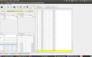
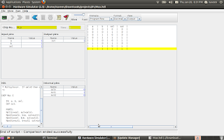
RAM8
RAM8:is a memory unit of 8 registers joined together to store 16*8 bits (16 byte). Based on the address (3bits) ,the Dmux8way device control the load signal for each Registers.
CHIP RAM8 {
IN in[16], load, address[3];
OUT out[16];
PARTS:
// load given as input of 8 way Demultipelxer so that 'load' is seperated to control each Registers
DMux8Way(in=load, sel=address, a=a, b=b, c=c, d=d, e=e, f=f, g=g, h=h);
/* 16-Bit register, load is given as each seperated lines
* If load[t-1]=1 then out[t] = in[t-1]
*/
Register(in=in, load=a, out=aa);
Register(in=in, load=b, out=bb);
Register(in=in, load=c, out=cc);
Register(in=in, load=d, out=dd);
Register(in=in, load=e, out=ee);
Register(in=in, load=f, out=ff);
Register(in=in, load=g, out=gg);
Register(in=in, load=h, out=hh);
// 16bit outputs from each Registers connected through 16bit 8 way multiplexer in order to get the outputs based on the Address
Mux8Way16(a=aa, b=bb, c=cc, d=dd, e=ee, f=ff, g=gg, h=hh, sel=address, out=out);
}

Tuesday, February 8, 2011
How to build a Memory for a computing System
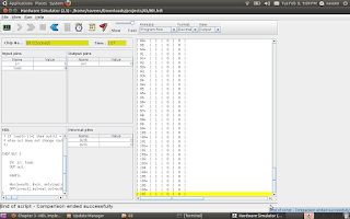
BIT STORE
The elementary functionality of a Computing System is that it should store data somewhere and should be collected it back whenever require. We can call this block as Memory unit of a computer. The Memory can be build using the sequential chip called flip-flop. Below HDL can store a bit . The small memory can Write and Read using the 'load' signal.
CHIP Bit {
IN in, load;
OUT out;
PARTS:
Mux(a=outb, b=in, sel=load,out=out1); //Mux input taken as the feedback of D-Flip Flop out
DFF(in=out1,out=out,out=outb);
}
================================================================================
Register
If a Bus(16bit) connected to 16 parallel a Bit chip ,then we can store 16bit at a time. This is known as Register.
CHIP Register {
IN in[16], load;
OUT out[16];
PARTS:
Bit(in=in[0],load=load,out=out[0]);
Bit(in=in[1],load=load,out=out[1]);
Bit(in=in[2],load=load,out=out[2]);
Bit(in=in[3],load=load,out=out[3]);
Bit(in=in[4],load=load,out=out[4]);
Bit(in=in[5],load=load,out=out[5]);
Bit(in=in[6],load=load,out=out[6]);
Bit(in=in[7],load=load,out=out[7]);
Bit(in=in[8],load=load,out=out[8]);
Bit(in=in[9],load=load,out=out[9]);
Bit(in=in[10],load=load,out=out[10]);
Bit(in=in[11],load=load,out=out[11]);
Bit(in=in[12],load=load,out=out[12]);
Bit(in=in[13],load=load,out=out[13]);
Bit(in=in[14],load=load,out=out[14]);
Bit(in=in[15],load=load,out=out[15]);
}
Thursday, February 3, 2011
ALU CHIP
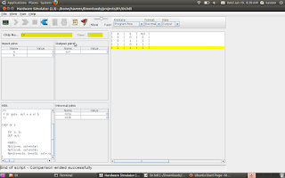
ALU (Arithmetic and Logic Unit):
The basic building block for a computer is ALU which can perform the basic Arithmetic and logical operations. The Chip creation using the HDL from the basic gates(AND,NOT,MUX,ADDER..etc) gives you the in site knowledge and interest for binary number operations. The below HDL ALU chip can perform 18 operations, potentially which can compute 64.
Follow the course The Elements of Computing Systems


CHIP ALU {
IN // 16-bit inputs:
x[16], y[16],
// Control bits:
zx, // Zero the x input
nx, // Negate the x input
zy, // Zero the y input
ny, // Negate the y input
f, // Function code: 1 for add, 0 for and
no; // Negate the out output
OUT // 16-bit output
out[16],
// ALU output flags
zr, // 1 if out=0, 0 otherwise
ng; // 1 if out<0, 0 otherwise
PARTS:
Mux16(a[0..15]=x[0..15], b[0..15]=false, sel=zx, out[0..15]=x1);
Mux16(a[0..15]=y[0..15], b[0..15]=false, sel=zy, out[0..15]=y1);
Not16(in[0..15]=x1, out[0..15]=notx1);
Not16(in[0..15]=y1, out[0..15]=noty1);
Mux16(a[0..15]=x1, b[0..15]=notx1, sel=nx, out[0..15]=x2);
Mux16(a[0..15]=y1, b[0..15]=noty1, sel=ny, out=y2);
And16(a[0..15]=x2, b[0..15]=y2, out=Andxy);
Add16(a[0..15]=x2, b[0..15]=y2, out=Addxy);
Mux16(a[0..15]=Andxy, b[0..15]=Addxy, sel=f, out=x3);
Not16(in[0..15]=x3, out=notx3);
Mux16(a[0..15]=x3, b[0..15]=notx3, sel=no, out[0]=ou1,out[1]=ou2,out[2]=ou3,out[3]=ou4,out[4]=ou5,out[5]=ou6,out[6]=ou7,out[7]=ou8,out[8]=ou9,out[9]=ou10,out[10]=ou11,out[11]=ou12,out[12]=ou13,out[13]=ou14,out[14]=ou15,out[15]=ou16);
Or(a=ou1, b=ou2,out= out1);
Or(a=ou2,b= out1,out= out2);
Or(a=ou3,b= out2,out= out3);
Or(a=ou4,b= out3,out= out4);
Or(a=ou5,b= out4,out= out5);
Or(a=ou6,b= out5,out= out6);
Or(a=ou7,b= out6,out= out7);
Or(a=ou8,b= out7,out= out8);
Or(a=ou9,b= out8,out= out9);
Or(a=ou10,b= out9,out= out10);
Or(a=ou11,b= out10,out= out11);
Or(a=ou12,b= out11,out= out12);
Or(a=ou13,b= out12,out= out13);
Or(a=ou14,b= out13,out= out14);
Or(a=ou15,b= out14,out= out15);
Or(a=ou16,b= out15,out= notzr);
Not(in=notzr,out=zr);
And(a=ou16,b=true,out=ng);
And(a=ou1,b=true,out=out[0]);
And(a=ou2,b=true,out=out[1]);
And(a=ou3,b=true,out=out[2]);
And(a=ou4,b=true,out=out[3]);
And(a=ou5,b=true,out=out[4]);
And(a=ou6,b=true,out=out[5]);
And(a=ou7,b=true,out=out[6]);
And(a=ou8,b=true,out=out[7]);
And(a=ou9,b=true,out=out[8]);
And(a=ou10,b=true,out=out[9]);
And(a=ou11,b=true,out=out[10]);
And(a=ou12,b=true,out=out[11]);
And(a=ou13,b=true,out=out[12]);
And(a=ou14,b=true,out=out[13]);
And(a=ou15,b=true,out=out[14]);
And(a=ou16,b=true,out=out[15]);
}
Monday, January 24, 2011
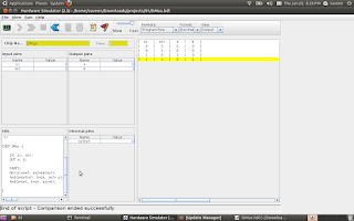
Half Adder & Full Adder
Half adder
CHIP HalfAdder {
IN a, b;
OUT sum, // LSB of a + b
carry; // MSB of a + b
PARTS:
Xor(a=a, b=b, out=sum);
And(a=a, b=b, out=carry);
}
Full Adder
CHIP FullAdder {
IN a, b, c;
OUT sum, // LSB of a + b + c
carry; // MSB of a + b + c
PARTS:
HalfAdder(a=c, b=b, sum=sum1, carry=carry1);
HalfAdder(a=a, b=sum1, sum=sum);
And(a=a, b=sum1, out=out1);
Or(a=carry1, b=out1, out=carry);
}
Adder 16 bit
CHIP Add16 {
IN a[16], b[16];
OUT out[16];
PARTS:
HalfAdder(a= a[0], b=b[0], sum= out[0], carry=carry1);
FullAdder(a= a[1], b=b[1], c =carry1, sum = out[1], carry = carry2);
FullAdder(a= a[2], b=b[2], c =carry2, sum = out[2], carry = carry3);
FullAdder(a= a[3], b=b[3], c =carry3, sum = out[3], carry = carry4);
FullAdder(a= a[4], b=b[4], c =carry4, sum = out[4], carry = carry5);
FullAdder(a= a[5], b=b[5], c =carry5, sum = out[5], carry = carry6);
FullAdder(a= a[6], b=b[6], c =carry6, sum = out[6], carry = carry7);
FullAdder(a= a[7], b=b[7], c =carry7, sum = out[7], carry = carry8);
FullAdder(a= a[8], b=b[8], c =carry8, sum = out[8], carry = carry9);
FullAdder(a= a[9], b=b[9], c =carry9, sum = out[9], carry = carry10);
FullAdder(a= a[10], b=b[10], c =carry10, sum = out[10], carry = carry11);
FullAdder(a= a[11], b=b[11], c =carry11, sum = out[11], carry = carry12);
FullAdder(a= a[12], b=b[12], c =carry12, sum = out[12], carry = carry13);
FullAdder(a= a[13], b=b[13], c =carry13, sum = out[13], carry = carry14);
FullAdder(a= a[14], b=b[14], c =carry14, sum = out[14], carry = carry15);
FullAdder(a= a[15], b=b[15], c =carry15, sum = out[15], carry = carry16);
}
Increment 16bit
CHIP Inc16 {
IN in[16];
OUT out[16];
PARTS:
Add16(a[0..15] = in[0..15], b[1..15] = false, b[0] = true, out = out);
}
Saturday, January 22, 2011
Tuesday, January 18, 2011
CHAPTER 1
Chip Design is as interesting as Programming. For building OR gate from NAND,we need to remember the basic theorems in Digital electronics.De_Morgan laws
DMUX
MUX
DMux4Way
CHIP DMux4Way {
IN in, sel[2];
OUT a, b, c, d;
PARTS:
DMux(in=in, sel=sel[1], a=mux1, b=mux2);
DMux(in=mux1, sel=sel[0], a=a, b=b);
DMux(in=mux2, sel=sel[0], a=c, b=d);
}
DMux8Way
CHIP DMux8Way {
IN in, sel[3];
OUT a, b, c, d, e, f, g, h;
PARTS:
DMux(in=in, sel=sel[2], a=mux1, b=mux2);
DMux4Way(in=mux1, sel[0]=sel[0], sel[1]=sel[1], a=a,b=b,c=c,d=d);
DMux4Way(in=mux2, sel[0]=sel[0], sel[1]=sel[1], a=e,b=f,c=g,d=h);
}

DMUX

MUX

DMux4Way
CHIP DMux4Way {
IN in, sel[2];
OUT a, b, c, d;
PARTS:
DMux(in=in, sel=sel[1], a=mux1, b=mux2);
DMux(in=mux1, sel=sel[0], a=a, b=b);
DMux(in=mux2, sel=sel[0], a=c, b=d);
}
DMux8Way
CHIP DMux8Way {
IN in, sel[3];
OUT a, b, c, d, e, f, g, h;
PARTS:
DMux(in=in, sel=sel[2], a=mux1, b=mux2);
DMux4Way(in=mux1, sel[0]=sel[0], sel[1]=sel[1], a=a,b=b,c=c,d=d);
DMux4Way(in=mux2, sel[0]=sel[0], sel[1]=sel[1], a=e,b=f,c=g,d=h);
}
